
Inhaltsverzeichnis
JRC NRD-515
Manufactured by Japan Radio Co., Tokyo
As a renowned manufacturer of shortwave receivers, transmitters and transceivers used primarily in maritime radio communications, the Japanese company Japan Radio Company launched their first receiver tailored to the budget of an amateur in 1977, nevertheless with an RF design corresponding to the company's reputation and manufactured in professional quality. The NRD-505 was followed by the NRD-515, which came at half the price at around $1000, it was the first receiver to be produced by JRC in larger quantities. Due to its excellent performance and straightforward operating concept, the NRD-515 soon became a radio amateurs reference receiver and also impressed with its appearance.

Technical data
- frequency range: 100 kHz - 30 MHz
- Frequency display: digital display, 100 Hz
- Frequency memory: 24 / 96 memories optional
1.6 - 30 MHz AM <2μV, SSB <0.5 μV / Selectivity: AM 4.5/10 kHz, SSB 2.2/4.5 kHz, CW (opt.) 0.5/3 kHz kHz (-6/-60 dB)
Power supply
- Mains operation: 117, 220 V
Dimensions
- 340 x 140 x 300 mm, weight 7.5 kg
Accessories
- NVA-515 Loudspeaker
- NDH-515 Memory module for 24 frequencies, NDH-518 Memory module for 96 frequencies
- NCM-515 Cable remote control and direct frequency input
- NSD-505 matching transmitter

Operation
The NRD-515, with its dimensions of 34 x 14 (19 with memory unit) x 30 cm and a weight of 7.5 kg, is a semi-professional tabletop receiver of medium size, its dimensions have been retained in the later successors from JRC. In addition to the receiver, the original equipment includes the 14 x 14 x 30 cm NVA-515 loudspeaker, but any 4 Ohm loudspeaker can be connected. To set up an amateur radio station, the NRD-515 can be operated in combination with an NSD-505 transmitter in similar design.
The power supply can be switched from 117 to 220 V AC, battery operation is not provided.
The dark grey / anthracite coloured front panel is divided into two parts. To the left is the rotary knob for the 30 MHz segments, with this and the large main tuning knob the reception frequency is set. Since one turn of the tuning knob only covers a range of 10 kHz, you will often use the small UP/DOWN switch at the top right to change frequencies quickly. A LOCK switch at the bottom right deactivates the tuning mechanism. The tuning knob transmits its impulses electronically to the PLL circuit.
Two rotary controls to the right and left of the main tuning knob adjust the radio frequency gain RF Gain and the volume AF Gain. Above this, at the top left, is a control that serves as a dual function in the medium-wave range as a preselector, and in the short-wave range as a BFO pitch control that regulates the note of Morse code signals.
At the bottom right, there is a rotary switch for selecting the electronic gain control AGC decay time constant or to turn it off for manual gain control operation, and the operation mode switch (AM, CW, USB, LSB, RTTY). Above this, in the upper row, is the rotary control for receiver fine tuning „Delta-F“; the frequency display is not altered by activating a frequency offset! Next to it is the passband tuning control, with which - unfortunately only in SSB mode - the passband curve of the IF filter can be shifted to eliminate adjacent interfering signals. The IF filter can be selected independently of the operation mode with the bandwidth switch located at the right next to it. In the original version, only the 2.4 and 6 kHz filters are fitted, the other filters are expensive options. In the upper front panel section, on the left, is the S-meter, which is designed as an analogue instrument and has a conservative characteristic. The red LED frequency display and LED indicators, that an external frequency memory or frequency offset operation are active ist next, followed by a row of switches for delta-F tuning, the noise blanker, the two-stage attenuator and the mains power switch. Two push-buttons above it switch the receiver to memory mode and to monitor mode when used together with a transmitter in an amateur radio station.
 In practical use, the NRD-515 still inspires the listener as much as it did at the time of its release. Renowned radio testers quickly declared the NRD-515 the ultimate reference receiver. The sensitivity of the NRD-515 is excellent and is really useful thanks to the mirror frequency rejection due to the high first intermediate frequency, „ghost signals“ will not appear. The selectivity is good with the ceramic 6 kHz IF filter in the not densely occupied broadcast bands; in the tropical bands and and in situations with strong interference from adjacent channel stations, the NRD-515 excels with its mechanical 2.4 kHz filter. With this and with the passband tuning carefully adjusted (it is unfortunately only active in SSB mode), the filter passband can be shifted and thus an undesirable interfering adjacent channel signal can be faded out, many „unintellegible“ signals can be heard. For broadcast station reception, some owners had an optional 3 - 4 kHz IF filter installed, for CW reception JRC offered a mechanical 600 Hz filter.
 To tune in a frequency, there was not only the possibility using the MHz switch, up/down switch and the large tuning knob, but also an external memory module. With the NDH-515 connected, 24 frequencies could be stored and recalled at the touch of a button, the „big“ memory module NDH-518 even had 96 memory channels.
For memory recall, the receiver must be set to Ext.VFO mode, the main tuning is then no longer effective, i.e. one cannot continue to scan a shortwave band from a stored frequency.
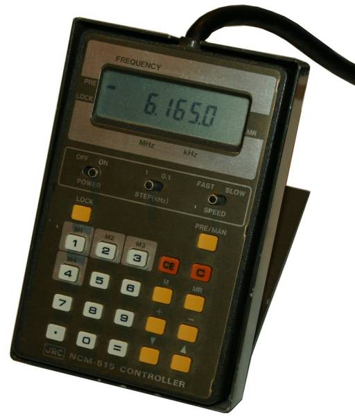
Another extremely useful accessory was built only in small numbers: the pocket calculator-like remote control NCM-515 is connected to the receiver via a cable, it enabled direct frequency entry via the keypad and also had 4 station memories.
 For the ultimate receiver control, an external controller was produced by the Swiss company Poly Electronic, the PFC-100 not only gave the NRD-515 far more memories, but also an alphanumeric station name display. However, this useful addition had its price; what is standard for a tabletop receiver today, would cost almost as much as an entire receiver 20 years ago.
Technical principle
After the attenuator circuit, the radio frequency signal has to pass through a 1.6 MHz high-pass filter active in short-wave operation and a 35 MHz low-pass filter and is fed to the first mixer, where it is converted to the first high intermediate frequency of 70.455 MHz. After an IF amplifier stage, the signal is mixed to the second intermediate frequency of 455 kHz, which is widely used in professional receivers. At this level, the noise blanker takes effect, the signal then passes through the IF filter bank, in addition to the standard filters, a CW and a additional filter can be fitted, and then, after IF amplification, it is fed to the demodulator. For SSB reception the BFO signal is mixed at this stage. The frequency synthesis is based on a digital PLL circuit, the control signals from the optional external memory circuit can control the VFO as an alternative to the tuning knob.
Components
The set is solid state.
