
Inhaltsverzeichnis
Technical principle
You find informations on the technical principle on every receiver model page.
Tuned Radio Frequency Receivers (TRF)
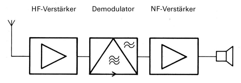
In the Tuned radio frequency receiver (TRF), the radio frequency signal from the antenna is selected in a tuned circuit and fed directly to the demodulator. In some cases, the radio frequency is fed to a tuned amplifier stage before demodulation; in most cases, the audio frequency is amplified after demodulation to give more than just headphone reception.
In the past, TRF receivers were classified according to the scheme (HF stages) - V (valve, i.e. demodulator) - (LF amplifier stages).
The simplest form of a TRF receiver is the detector receiver, in which the signal is tuned in an resonating circuit consisting of a variable capacitor and coil and then fed to a detector or diode without amplification, the audio signal drives the headphones without any further amplification (scheme 0-V-0).
In more complicated sets, a radio frequency amplifier is connected before the detector stage (scheme 1-V-0), the RF amplifier stage is demanding and in the early sets, performance at higher frequencies and selectivity was quite poor. The selectivity can be improved with two tuned circuits, but their tuning capacitors must act in perfect synchronisation.
For loudspeaker reception, usually an audio frequency preamplifier and an audio output stage are fitted (example: two HF preamplifier stages, demodulation, two LF stages: 2 - V - 2).
Audion (Regenerative Receiver)
The audion (or regenerative receiver) is also a kind of tuned radio frequency receiver. The radio frequency is amplified in the audion tube, the amplified radio frequency is then fed back to the input with an adjustable feedback („regeneration“) and the amplification factor is increased. The reception performance can be improved by compensating the attenuation and the receiver becomes more selective. The demodulation takes place in the same tube at the non-linear tube characteristic and the audio frequency then can be fed to the headphones through a low-pass filter (the RF has been fed back in the regeneration circuit).
At a certain amount of regeneration, the circuit begins to oscillate, the reception becomes distorted and the circuit, which now acts as an oscillator, radiates high-frequency via the antenna, this might cause interference in receivers in the vicinity. Therefore, the regeneration must be regulated carefully; just before onset of the oscillation, the regeneration is most effective, the performance is the best and the selectivity at it's maximum.
The Superregenerative Receiver or „pendulum audion“, in which an oscillator switches the operation of the audio tube constantly between amplification and oscillation and the manual adjustment of the regeneration is no longer necessary. Even this design belongs to the TRF receiver circuits. Superregenerative receiver technology can be found in post-war German VHF receivers to save tube costs.
Superhet
 In the Superheterodyne Receiver, also known as a single conversion superhet or superhet, the problem of non-linear radio frequency amplification is circumvented in a very elegant way by mixing the antenna RF signal with the signal of a variable oscillator in a mixer stage, so an intermediate frequency is generated. It is much easier to construct suitable amplifiers and filters for this fixed frequency, then the intermediate frequency is fed to the demodulator stage.
In a single conversion superhet, the signal coming from the antenna has to pass through a tuned circuit (consisting of a coil and a variable capacitor) and is then mixed with the signal from the tunable oscillator. The variable oscillator must run absolutely in synchronisation with the antenna tuned circuit, that's why double variable capacitors are to be used.
The oscillator frequency is usually higher than the desired operation frequency, the intermediate frequency is generated through subtractive mixing in the mixer stage tube.
If additional high-frequency amplification is desired to achieve a higher sensitivity, a further tuned circuit is implemented after the RF amplifier; in this case a triple variable capacitor must be used, which is a more complex and expensive precision component.
The intermediate frequency is amplified in one or more IF amplifier stages, which are easier to construct. Also the IF filters responsible for the selectivity of the receiver are installed here. The signal is then red to the demodulator and then to an AF preamplifier and final stage.
A problem of the superhet receiver circuit is on the one hand the necessity of excellent shielding and temperature constance of the oscillator, on the other hand the occurrence of mirror frequencies. In the mixer stage, not only subtractive mixing (F(ant)-F(osc)) occurs, but also additive mixing (F(ant)+F(osc)), which can cause a station to appear two times on the dial. The mirror signal appears in a distance of the double IF, filtering has to be used to deal with the problem of mirror frequency suppression.
The designers choice of the intermediate frequency depends on the frequency range of the receiver: with a long-wave receiver, a low intermediate frequency is more favourable, since high selectivity filters can be constructed with simple bandpass filters and the mirror frequency is still in acceptable distance of the wanted signal on the dial. For example, in the Swiss receiver E41, the intermediate frequency is 70 kHz for the low frequency ranges around long and medium waves.
For receivers covering the shortwave range, where the double IF mirror is very close to the operating frequency on the dial, a high IF is chosen. But for high intermediate frequencies, the quality of bandpass filters (LC) is not sufficient, so that ceramic, crystal or mechanical filters are used. In addition, it takes more effort to construct IF amplifiers operating at higher frequencies.
A typical intermediate frequency often used in domestic radios is 455 kHz.
Double conversion superhet
 Since receiver developers when deciding about the intermediate frequency always have to find a compromise between the risk of mirror frequencies appearing (the appearance of a double of a strong signal as a „ghost station“ in the wrong place on the dial should be prevented) and selectivity, the principle of the double conversion superhet or double conversion is used in high-quality receivers.
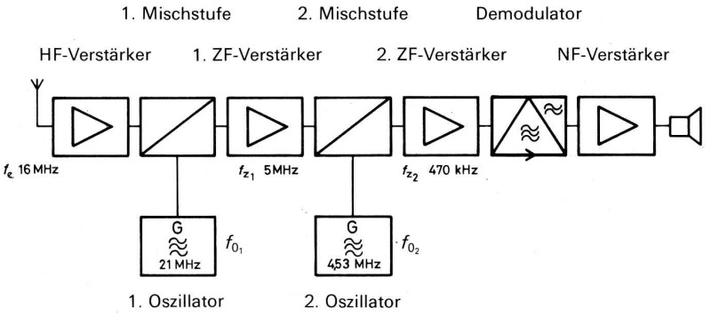
In double conversion superhets, the antenna signal is mixed with an oscillator signal on a much higher frequency then the operation frequency to generate a first intermediate frequency in the range of, for example, 5 MHz. This has to pass through band filters, IF amplifier stages and then is converted to a second intermediate frequency with a second oscillator signal. The final filtering and amplification, which determine the receiver selectivity, can be done with much simpler means.
The first intermediate frequency, which is usually selected as high as possible, protects against image frequencies that can appear in the distance of the double IF on the dial and - in the example of an intermediate frequency of 5 MHz when it appears with a distance of 10 MHz - it can easily be filtered out: a high first IF results in good image frequency rejection.\ At the lower second intermediate frequency, better quality IF filters can be constructed with reasonable effort and fewer IF amplifier stages are needed: a lower second IF results in easier-to-achieve high selectivity.
CW reception
 Morse code signals, which are generated by simply switching a non-mobulated radio frequency signal on and off (A1), cannot be heard in the headphones after a simple detector, or only a slight hiss can be heard.
In order to make these Morse code signals audible, an oscillator signal must be added to the antenna signal, which differs from the antenna signal by the frequency amount, according to the desired audible frequency in the headphones. This oscillator, which is to be switched on for telegraphy mode (referred to as A1, unmodulated telegraphy), is called „telegraphy oscillator“ or BFO (Beat Frequency Oscillator).
Usually, in addition to the switch for activating the BFO (sometimes referred to as „telegraphy“ or „Tg. umodulated“ mode), also a pitch control and in some units, a level control for the BFO signal, can be found.
In single sideband mode (SSB), only one sideband of an AM signal (which consists of two identical symmetrical sidebands and the carrier signal in between) is transmitted. In AM mode, most of the transmitting power is wasted for the two identical sidebands and tghe carrier, so a transmitter can thus be used more efficiently when only one sideband with the content is transmitted and no energy is wasted for the carrier signal not containing information.
To make a single sideband signal audible, an auxiliary carrier must be inserted in the receiver, which replaces the carrier signal coming from the transmitter. The BFO can also used for this function in simple receivers. With the pitch control, the distance between the subcarrier signal and the received sideband signal must be adjusted in a way, that the speaker's voice sounds natural and speech neither sounds bassy or squeaky like Mickey Mouse.
Single-sideband reception
 In high end receivers, there are technically more complex circuits for single sideband reception.
The received single sideband signal (without carrier), which can hardly be heard in normal AM mode, is mixed after conversion to the intermediate frequency with two selectable oscillator frequencies, which are at a fixed distance from the intermediate frequency. With corresponding specific filters, either the upper sideband (USB) or the lower sideband (LSB) can be selected.
With appropriate narrow-band SSB filters of 2.5 - 3.6 kHz, dimensioned for optimum speech intelligibility, a weak signal affected by adjacent channel interference can be made intelligible.
FM reception
 Frequency-modulated transmissions, in which a slight variation of the transmission frequency, rather than the amplitude of the sidebands, are carrying the modulated speech or audio information, were used in military communications at the end of World War II. In the VHF range, wider channel spacing is possible, FM transmissions are less susceptible to atmospheric interference and speech intelligibility is much better.
In an FM receiver, in almost al cases, the superhet principle is used. The antenna signal is converted to an intermediate frequency of typically 10.7 MHz, usually after a radio frequency amplifier stage.
The signal is then amplified in the IF amplifier. Residual amplitude modulation is eliminated by a massive amplification of the signal and then clipping it in the limiter. Demodulation takes place in the discriminator, a special demodulator circuit.
In order to improve speech intelligibility, the high frequencies in the audio spectrum of FM broadcast stations are boosted on the transmitter side. After demodulation, the high frequencies are attenuated in an RC element, which is called de-emphasis. In Europe, typically a time constant of 50 μs is used for de-emphasis; in the USA, 75 μs is standard in broadcasting stations, that explains why American FM radios used to have a duller sound.
Documents
The textbooks of the Swiss Army signal troops, with which the basics can be learned in a step by step self-study approach, are an excellent study source, but they are available only in german (and french) language: