
Inhaltsverzeichnis
Barlow Wadley XCR - 30 FM
Manufactured by Barlow's Television Co, P.O.Box 23, New Germany, Natal, Rep. of South Africa.
Around 1970, a portable receiver was quite a sensation among shortwave listeners. Based on the Wadley Loop circuit, which was first used in the commercial English receiver Racal RA-17L, Dr. T. L. Wadley had designed a travel receiver, which was manufactured by the South African company Barlow's Television Co. and was also imported to Europe.
This portable receiver had, among others, the Grundig Satellit receivers, the Zenith Transoceanic, the Panasonic RF-2200 and the Sony Earth Orbiter CRF-5080 / 6090 as competitors. Due to its circuit design, the Barlow Wadley XCR-30 was a good performer even in ECSS mode (reception of weak AM stations in single sideband mode with the BFO replacing the original carrier) and had a dial accuracy of 5 kHz on the linear analogue dial.
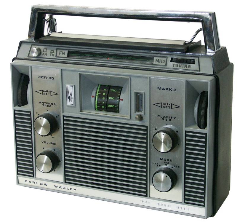
You will not often encounter the variant with the FM broadcast band tuner installed underneath the carrying handle.

Technical data
- Frequency range: 500 kHz - 30 MHz
- Frequency dial: analogue linear dial, 5 kHz
- Frequency memory: none
Power supply
Dimensions
- 295 x 185 (235 with carrying handle) x 100 mm, weight 4.3 kg
Accessories

Operation
The receiver is 295 x 185 (235 with carrying handle) x 100 mm wide and has a weight of 4.3 kg; it has a sturdy metal cabinet to avoid interference in the 45 - 75 MHz range due to the mixing process. There is a carrying handle on the top face and a shortwave broadcast band table can be folded out underneath. The back of the unit can be unscrewed to access the battery compartment with space for six UM1 mono cells.
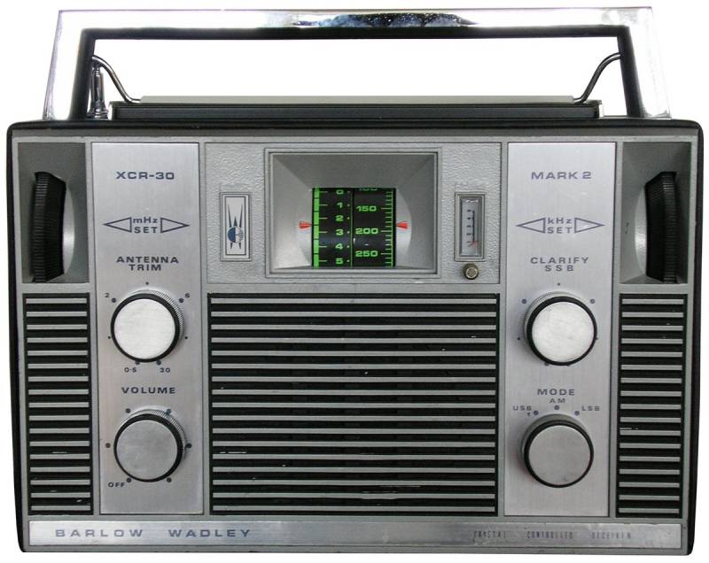
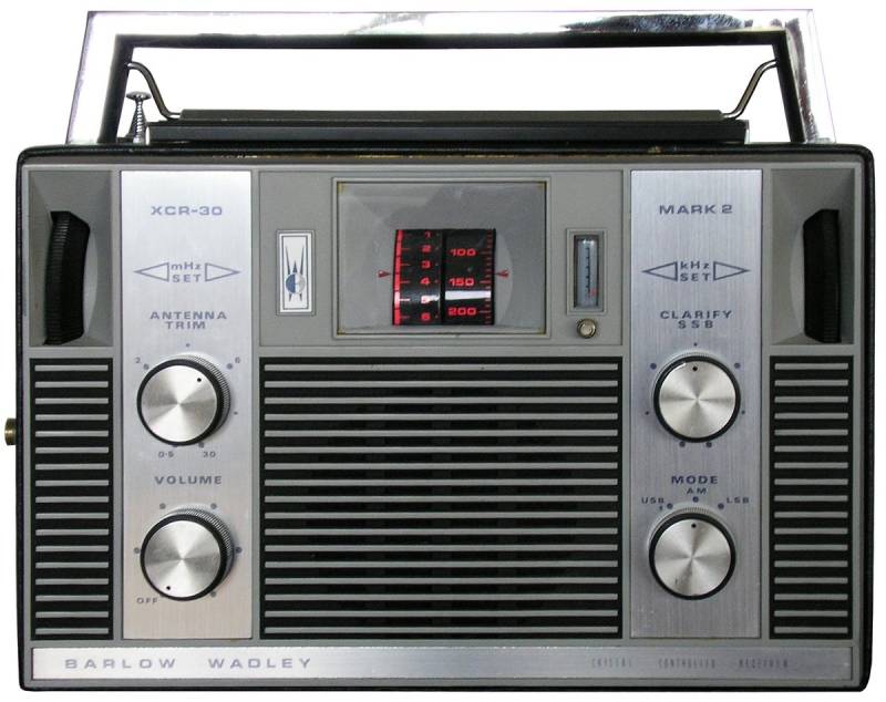
The front panel is dominated by the two-part frequency dial. The dial on the left indicates the megahertz digit and the MHz tuning knob at its left is used to set the MHz bands. The right dial indicates the kHz digits, the dial markers with their light green digits indicate the frequency with a spacing of 50 kHz, the 10 kHz lines in between allow a frequency reading to 5 kHz. The kHz tuning is done with the right frequency tuning knob, the control is sensitive to be operated. Just right of the frequency dial, the S-meter with a 1 - 5 division can be read in a small window, it tends to read high. The small knob below the S-meter is used to calibrate the dial by adjusting the oscillator.
Furthermore, there are four large knobs on the front panel. At the bottom left is the volume control, which is combined with the power switch. The knob above tunes the preselector, it has rudimentary markings from 0.5 - 30 MHz, the preselector ranges are switched with micro switches when the knob is turned. The knobs on the right side are used to operate the fine tuning (Clarify, used mainly for SSB reception) and to switch the operation mode USB / AM / LSB. In the Pro version, the bandwidth switch for the 6, 3 and 1.5 kHz filters is located below the operating mode switch.

Only the FM version comes with the FM tuner built in below the carrying handle. The left AM/FM button switches between the normal reception circuit and the FM tuner, which is tuned with a knurled wheel located at the right of the horizontal FM frequency dial.
The connectors for antenna and earth, which came as unusual 3 mm sockets, are located on the top face of the unit, and on the left face the sockets for headphones (3.5 mm jack) and an external 9 volt power supply. The 9 cm diameter loudspeaker radiates from the middle of the front panel; the output power of 0.4 watts is sufficient. The radio, which was constructed wit ha good perice - performance ratio in mind, lacks a few extras such as dial illumination, tone control and other signal processing options, which are not absolutely necessary for successful reception.
The signal path is somewhat complicated, as with all receivers based on the Wadley loop circuit. The signal from the antenna is fed via the preselector with the ranges 0.5 - 2 / 2 - 8 and 8 - 30 MHz and an amplifier stage to the first ring mixer, where the oscillator frequency of 45.5 - 74.5 MHz, tuned with the MHz wheel, is mixed, resulting in the high first intermediate frequency of 45.2 MHz. In the second mixer stage, the oscillator frequency of 42.5 MHz is subtracted, resulting in a difference of 2 - 3 MHz which acts as second IF. After another conversion to the usual second IF of 455 kHz, the signal passes through the filter bank (in the Pro version, different filters were used here, in the original version, the passband of the IF filter was electronically extended for AM reception) and is fed to the diode or product detector for AM and SSB reception. The ingenious circuit, which could be realised with a reduced number of components, resulted in a very high frequency accuracy of less than 5 kHz on the analogue frequency dial (what was extraordinary in those years), with good sensitivity and mirror frequency rejection.
Due to the circuitry, the operation is not quite foolproof, butis easy to be learned within minutes. After switching on, the MHz position is selected with the MHz dial and peaked to S-meter maximum. When the kHz control is in zero position, the receiver can be switched to USB / t position with the operating mode switch and calibrated to zero beat (i.e. until the whistling tone becomes lower and disappears) with the small rotary control below the S-meter. Now switch back to AM and set the kHz digit of the reception frequency with the right-hand tuning knob. The preselector control marked ANTENNA TRIM is now tuned to a maximum S-meter deflection in the correct range near the corresponding frequency mark and the station becomes audible. In case of strong AM interference or for SSB/ECSS reception, use the the CLARIFY knob located above the mode switch for fine tuning, the frequency display remains unaffected. Be careful, if the CLARIFY control is far from the centre position, the received frequency may deviate from the indicated frequency by 5 to 10 kHz.
The Barlow Wadley, as a portable receiver with quite good stability, still offers much to the shortwave listener and is suitable for DX. The somewhat inaccurate frequency display and operation scheme that takes some experience is compensated for by the absence of any birdies generated by PLL circuits. Battery consumption is minimal thanks to the analogue circuitry and cannot be compared to early world band receivers with digital frequency displays.
Apparently, the manufacturing and final inspection at Barlow was subject to daily fluctuations, the first transistor was susceptible to electrostatic discharge and the single circuit board to cold solder joints and hairline cracks, so that a second-hand unit should be tested before purchase.
The variant with the added FM band is not common: the additional FM tuner has its own horizontal dial and tuning knob, making the XCR-30 a real holiday travel companion….
My XCR-30 was never meant to replace the Sony ICF-2001D as my favourite travel set, but it deserves a place of honour on my desk as an oldie thanks to its fascinating circuitry, unobtrusive exterior and always amazing reception performance.
Technical principle
Double conversion, Wadley Loop circuit.
Components
The set is equipped with semiconductors.
Technical documentation
- Service Manual with schematics, inkl. FM-Tuner
