Inhaltsverzeichnis
AN/ART-13
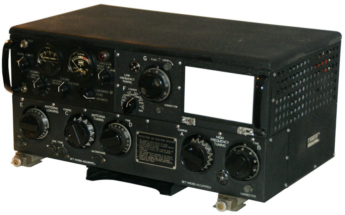
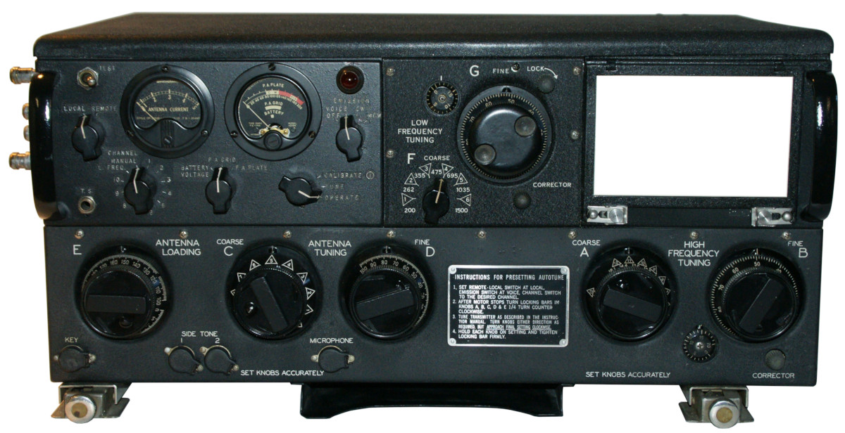
Transmitter AN/ART-13 or T-47; manufactured by Collins.
The aeronautical radio transmitter ATC developed by Collins around 1940 was a common transmitter in American aircraft, the improved version AN/ART-13 became the standard transmitter in American aircraft; modified versions were also used in civil aviation (especially after the war) and in vehicles.
Technical data
- Principle: transmitter AN/ART-13 or T-47
- Frequency range: 0.5 - 1.5 MHz; 2 - 18 MHz
- Transmission power A3 approx. 100 W
Power supply
- Batteries: 28 V DC aircraft on-board voltage; the plate voltage is generated by means of rotary converter DY-11 or DY-12 or newer version DY-17 or DY-17A (available after WWII, these converters are interchangeable in principle). 28 V DC was connected directly to the tube heater; the plate voltages 400 V and 750 V were wired in series to achieve 1150 V plate voltage in transmit mode. A barometric switch reduces the plate voltage to 750 V at flight altitudes above 20,000 - 25,000 feet to prevent sparkover.
Dimensions
- 600 x 346 x 273 mm, 31.75 kg
Accessories

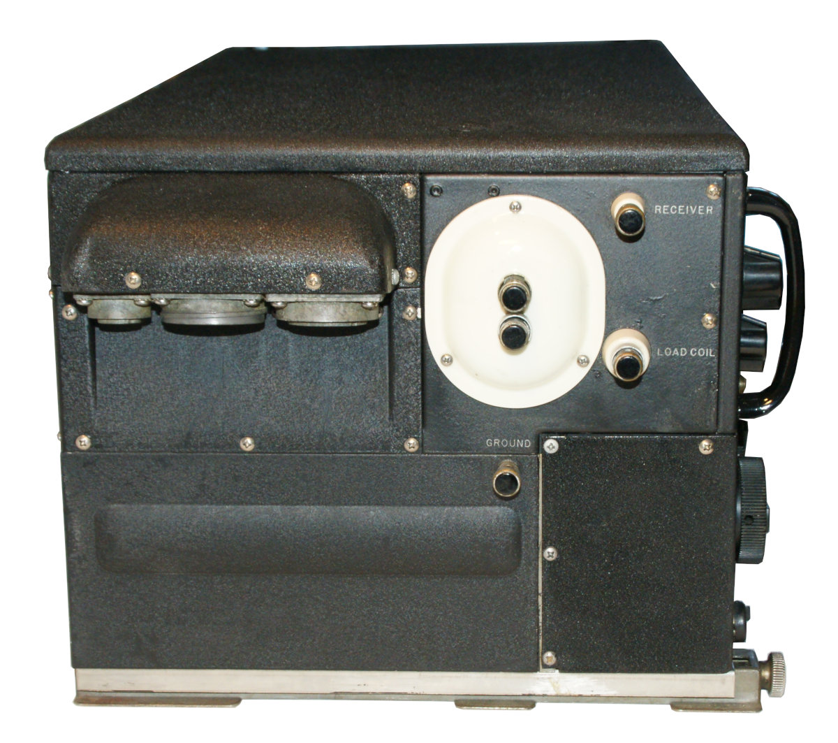
- In addition to the standard set with coverage of the shortwave ranges, plug in units with coverage of the VLF range were available; the older LFO Frequency Oscillator O-16 covers the range 0.2 - 1.5 MHz (AN/ART-13 system), the newer O-17 only the frequencies 0.2 - 0.6 MHz (AN/ART-13A).
- With a crystal oscillator add-on CDA-T manufactured by Communications Company, Inc. either four frequencies in the VLF range or 20 shortwave frequencies could be preselected. This addition required considerable modification of the original circuit, the model thus modified is labelled AN/ART-13B.
- Mounting Base MT-284/ART-13 for mounting the transmitter in the aircraft
- Control Unit C-87/ART-13 for remote control of the transmitter with a choice of ten preset channels
- Antenna Loading Unit CU-32 for adjusting a towed antenna in the aircraft or a shortened antenna of the ground station in the VLF range
- Dynamotor (rotary converter) DY-17 with mounting plate MT-164
- Microphone T-17 or T-30
- Morse key J-37
- Headphones HS-33 or HS-38
Operation
The AN/ART-13 transmitter was used in many American Air Force aircraft. After the end of World War II, many of the sets were sold as surplus and civilian airlines also stocked up on the reliable sets for long-range shortwave aeronautical radio communication. The ART-13 was also used by the Swiss airline Swissair.
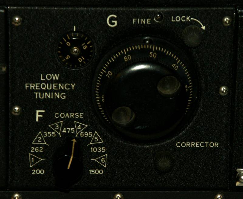
The transmitter could not only be tuned manually, but for the first time in the 1940s, an „autotune“ mechanism was used to mechanically preselect frequencies; with the additional crystal oscillator, twenty frequencies could be preselected.
For manual tuning, the „CHANNEL“ channel switch is set to the „MANUAL“ position; this is the only way to tune the set without causing damage to the autotune system. To pre-tune channels, proceed as described in the manual. For local operation, the LOCAL/REMOTE switch must be in the LOCAL position, the operation mode is selected with the EMISSION switch, VOICE for AM, CW for telegraphy and MCW (modulated CW) for transmissions in tone telegraphy, which can be received by the remote station using an AM receiver without the use of a BFO.
 The red pilot lamp lights up and indicates readiness for operation, while the AUTOTUNE mechanism is activated for a frequency change (approx. 25 sec.), it goes out for a moment; the light indicates that the set is ready to transmit or antenna tuning. In MANUAL mode, buttons A - E can be moved; in AUTOTUNE mode, when pre-tuning a channel, the locking bar must be turned 90° anti-clockwise while holding the dial.
The exact tuning procedure using calibration points in the calibration table supplied is described in detail in the manual. First set the coarse tuning C COARSE to 1 and search for the calibration point in the calibration table that is closest to the operating frequency. The A HIGH FREQUENCY TUNING COARSE control is then set to the specified position, followed by the B FINE control. In the CALIBRATE switch position, the next calibration point is searched for and B is tuned to zero beat. The calibration switch is now set to TUNE and the correction is set according to the specification in the calibration table. Then set the correct position of control B for the desired operating frequency (which does not correspond to the calibration frequency) according to the calibration table.
Now set the EMISSION operating switch to the CW position for tuning; with the measuring instrument switch set to the P.A.GRID position, the pointer should now point to the marked P.A.GRID range. Now set the instrument switch to the P.A.PLATE position (anode current), set the D ANTENNA TUNING FINE control to 0 and turn the ANTENNA LOADING control to the TEST position with the switch at the top left until a dip, a drop in the antenna current, indicates resonance.
If no resonance dip is found, C is set one level higher and a dip is searched for again by turning ANTENNA LOADING E. This procedure is repeated until a resonance-indicating dip / drop in the anode current is found, i.e. up to the „8“ range. If a position with resonance is now found, the operating switch is moved to the OPERATE position and control D ANTENNA TUNING FINE is slowly turned upwards and tuned to minimum anode current or resonance with E. When you have reached the top position 100 with control D, you can increase C one step and start again with control D at 0 and continue to increase carefully until the display instrument drops down into the „CW“ range in the event of resonance. Further information can be found in the technical manual.
Technical principle
Tube configuration
V101 (837, HF oscillator); V102 (1625, 1st multiplier stage); V103 (1625, 2nd multiplier stage); V104 (813, power output stage); V105 (811, modulator); V106 (811, modulator);
V201 (12SJ7, 1st audio amplifier); V202 (12SJ7, 2nd audio amplifier); V203 (6V6, sidetone amplifier); V2201 (12SL7, 200 kHz calibration oscillator, frequency tripler stage); V2202 (12SA7, mixer stage); V2203 (12SL7, signal detector, A2 tone generator);
in LFO O-17: V2601 (1625; LF oscillator); in the CDA-T crystal oscillator V801 (6AQ5, HF oscillator) resp. in the LF version V802 (1625, LF oscillator)