
Inhaltsverzeichnis
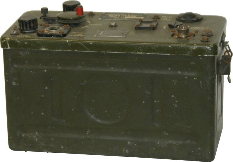
Wireless Set No. 31 AFV
Used by the Royal Signal Corps.
The British Wireless Set No.31, which was to replace the small radios W.S.18, 68 and 46, was based on the technically closely related American set SCR-300-A (BC-1000). The first prototypes were ready at the end of 1945/46, production started in November 1946 and the set was delivered to the infantry between 1947 and 1949.
The sets were sold as military surplus in Switzerland and elsewhere and were often modified; my sets also have such a past. They were used by an engineer as a „car telephone“ in an American road cruiser.

Technical data
- Frequency range: 40 - 48 MHz, 41 channels with 20 kHz channel spacing
- Frequency display: Analogue dial
- Frequency memory: none
- Transmit power: FM 0.3 watts
Power supply
- Batteries: Heater voltage 4.5 V; anode voltage 90 V and 150 V
- Homemade mains power supply for fixed operation
Dimensions
- 305 x 432 x 152 mm, weight 10.2 kg
Accessories
- Rod antenna approx. 150 cm

Operation
The W.S.31 AFV vehicle radio operates in the military VHF range 40 - 48 MHz and uses frequency modulation. In contrast to amplitude-modulated radios, the connection was less susceptible to interference from ignition sparks.
The tuning knob / channel selector switch with a mechanical lock is located on the left of the front panel, channels 0 - 40 have 200 kHz spacing, four channels for communication with the Wireless Set No.88 are labelled A - D, and the set can be calibrated with an internal oscillator signal in the CAL positions at 43.0 / 47.3 MHz. At the bottom left is the volume control and next to it the connection for headphones / headset with transmit/receive switch, which was modified on my set. To connect a microtelephone, it was converted to a Noval tube base; the microtelephones and also a separate homemade control unit with a hand-held microphone were equipped with corresponding plugs.
At the top right is a pushbutton for calibrating the set, the dial window with the channel display (with a mechanically movable calibration mark) and the antenna connection, which was converted to a coaxial socket.
Technical principle
The receiver works as a double conversion superhet with a RF amplifier stage, the receiver oscillator oscillates at half the operating frequency and then passes through a doubler stage, only the early Mk I sets have an automatic squelch circuitry. By pressing the Calibrate button, the 10th and 11th harmonics of the 4300 kHz oscillator are fed to the second mixer tube and can be tuned to „zero beat“.
In transmit mode, the modulator signal is mixed with the main oscillator (17.85 - 21.85 MHz) and then fed to a frequency doubler stage; after mixing with the 4.3 MHz oscillator signal, the signal is fed to an RF output stage and the antenna.


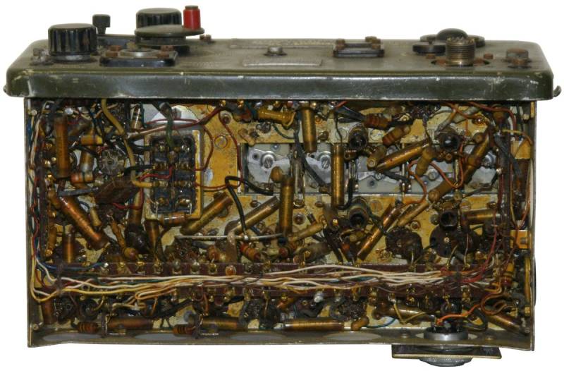
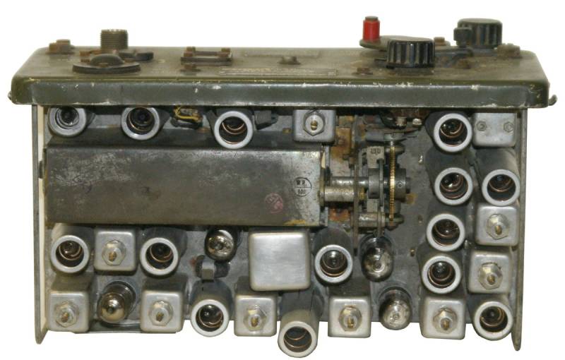
Components
The set is equipped with tubes:
- V1 CV807 (3A4): Power amplifier, power amplifier
- V2 CV807 (3A4): Mixer, crystal oscillator
- V3 CV785 (1T4): Doubler
- V4 CV785 (1T4): Oscillator
- V5 CV1785 (1L4): AVC
- V6 CV785 (1T4): HF amplifier
- V7 CV1785 (1L4): 1st mixer
- V8, V9 CV785 (1T4): IF amplifier
- V10 CV782 (1R5): 2nd mixer, crystal oscillator
- V11 CV785 (1T4): IF amplifier
- V12, V13 CV1785 (1L4): Limiter
- V14 CV753 (1A3): Discriminator
- V15 CV784 (1S5): Discriminator, NF Amplifier
- V16 CV784 (1S5): LF amplifier
- V17 CV1785 (1L4): DC amplifier
- V18 CV784 (1S5): Squelch Oscillator
Technical documentation
Wireless Set. No. 31 AFV - S/N M.R.1486
Inspection
 First, the home-made power supply unit was inspected. When looking at the handdrawn circuit diagram, the 6.3 V voltage from the heaters winding of the transformer is rectified via a bridge rectifier and reduced to the 4.5 V required for the tube heating with a wire-wound regulating resistor. The anode voltage of 150 V is rectified in a diode, stabilised with a 0A2 and the receiver anode voltage of 90 V is obtained with a voltage divider; electrolytic capacitors filter both DC voltages.
The voltages are made available at a loctal tube socket, where the connecting cable to the W.S.31 is plugged in. Only after the plug is inserted and the voltage is applied to the power supply unit, the pilot light come on. The developer has installed a switching contact that only turns on the power supply unit when the power cable is plugged in. It is therefore not possible to check the voltage in „idle mode“.
 The W.S.31 AFV was also modified for the connection of a headset and aerial: Noval tube sockets are used to connect a Mikrotel with a retrofitted push to talk button, a red dot marks the 12 o'clock position. The aerial connection was converted to a PL39 coaxial connector, a simple wire aerial is connected here, the RF of the Leader LSG-17 signal generator is coupled here with a few windings.
After powering up the set, a hiss can be heard from the receiver, and a strong whistling tone is heard when the signal generator passes through channel two above 40 MHz. After releasing the DIAL LOCK, the W.S.31 is tuned to channel 8 and the whistling tone from the signal generator becomes audible at around 42 MHz. At least the receiver part seems to work on the W.S.31 AFV with serial number M.R.1486.
 The following modifications have been made to this W.S.31 S/N M.R.1486: Replacement of the power supply; replacement of the handset connector; replacement of the antenna connector with PL39; the critical square 10 nF capacitors, which are prone to failure, were apparently largely replaced or more reliable types already used at the factory.
Revision
So far only contact maintenance and cleaning, next step would be to test the transmitter stage in an artificial load.
Wireless Set. No. 31 AFV - S/N M.R.4327
Inspection
 The W.S.31 S/N 4327 is operated with the same home-made power supply unit as described above. The connecting cable to the W.S.31 is plugged into the loctal base.
The W.S.31 AFV was modified in the same way to connect the headset and aerial: Noval tube sockets are used to connect a Mikrotel with a retrofitted PTT button, a red dot marks the 12 o'clock position. The aerial connection was converted to a PL39 coaxial socket, a simple wire aerial is connected here, the RF of the Leader LSG-17 signal generator is coupled here with a few windings.
After powering up with the set switched on, a hiss can be heard from the receiver, and a strong whistling tone is heard when the signal generator passes through channel two above 40 MHz. After releasing the DIAL LOCK, the W.S.31 is tuned to channel 8 and the whistling tone from the signal generator becomes audible at around 42 MHz. At least the receiver part seems to work on the W.S.31 AFV with serial number M.R.1486.
 The following modifications have been made to this W.S.31 S/N M.R.1486: Replacement of the power supply, loktal connector to the power supply; replacement of the Mikrotel connector; replacement of the antenna connector with PL39; the critical square 10 nF capacitors, which are prone to failure, were apparently largely replaced or more reliable types already used at the factory.
Revision
 So far only contact maintenance and cleaning, next step would be to test the transmitter stage in an artificial load.
Wireless Set. No. 31 AFV - S/N M.R.1609
Inspection
 The W.S.No.31 S/N 1609 set is closest to the original in terms of its front panel. The plug connectors for the microphone and headphones are also unmodified, as is the aerial connection.
However, the cabinet is missing, practically all the tubes have been removed and the set can at best be regarded as a spare parts donor. Surprisingly, all 10 nf capacitors are identical to the capacitors used in the other sets.
 In the advert opposite, W.S.31 from British Surplus were offered for sale by Bühler Elektronik, Zurich 3, at a favourable price of 67.50 Fr. It is pointed out that the PTT regulations must be observed when operating the transmitter - as far as I know, however, in the 1960s the VHF range was only authorised for military use and not for radio amateurs or private individuals.
Whether the two sets described above, which were converted into vehicle radios by a Zurich engineer, were allowed to be operated with a PTT licence remains to be seen, but they were in use for a long time.


