
Inhaltsverzeichnis
AN/GRC-3 radio family - 8
Manufactured by various U.S. manufacturers.
Technical data
- Frequency range: SW / VHF
- Frequency display: Analogue dial
- Frequency memory: 80 channels, 100 kHz channel spacing; two mechanical presets
Power supply
- Batteries: the four plate voltages 450 V, 150 V, 105 and 85 V, grid voltages and the heater voltage of 6.3 V are provided by the power supply unit PP-112, which is powered by the 24 V on-board vehicle voltage. The PP-109 power supply unit also allows operation from a vehicle with 12 V on-board voltage.
Dimensions
- mm, weight kg
Accessories
- Handset H-33/PT
- Chest control box GSA-6 with intercom set H-63/U
- Microphone M-29/U
- Headphones CW-49507 or loudspeaker LS-166/U
- Control box C-375/U with connections for microphones, headphones and the three channels of the AM-65 on-board amplifier.
- Relay unit C-435/GRC, or local control unit C-434/GRC of the remote control system GRA-6. The radio can be remotely controlled from the remote control unit C-433/GRC via a field telephone line.
Station material
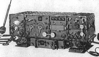
The AN/GRC-3 - 8 radio station was used in various configurations and with different frequency coverage in wheeled and tracked vehicles of NATO, the USA and also the German Bundeswehr.
| AN/GRC-3 | RT-66, R-108, RT-70, AM-65 | transceiver, auxiliary receiver, low power transceiver, on-board amplifier | 20 - 27.9 MHz (armoured vehicles), 16 + 0.5 W, 80 channels |  |
| AN/GRC-4 | RT-66, RT-70, AM-65 | transceiver, low power transceiver, on-board amplifier | 20 - 27.9 MHz, 16 + 0.5 W, 80 channels |  |
| AN/GRC-5 | RT-67, R-109, RT-70, AM-65 | transceiver, auxiliary receiver, low power transceiver, on-board amplifier | 28 - 38.9 MHz (artillery), 16 + 0.5 W, 120 channels | |
| AN/GRC-6 | RT-67, RT-70, AM-65 | transceiver, low power transceiver, on-board amplifier | 28 - 38.9 MHz (artillery), 16 + 0.5 W, 120 channels | |
| AN/GRC-7 | RT-68, R-110, RT-70, AM-65 | transceiver, auxiliary receiver, low power transceiver, on-board amplifier | 38 - 54.9 MHz (infantry), 16 + 0.5 W, 170 channels | |
| AN/GRC-8 | RT-68, R-108, RT-70, AM-65 | transceiver, auxiliary receiver, low power transceiver, on-board amplifier | 38 - 54.9 MHz (infantry), 16 + 0.5 W, 170 channels | |
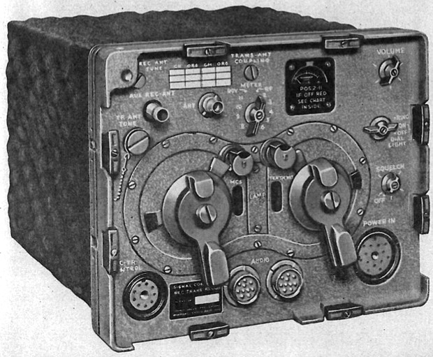 The medium-power transceiver can be set to 16 and 2 watts output power. The sets are frequency modulated, operate with a frequency deviation of ± 20 kHz, the channel spacing is 100 kHz.
- RT-66: 20 - 27.9 MHz, 80 channels, mechanised troops
- RT-67: 28 - 38.9 MHz, 120 channels, artillery
- RT-68: 38 - 54.9 MHz, 170 channels, infantry
The receiver acts as a double conversion superhet. A first crystal oscillator is switchable between 15.55 - 22.55 MHz in 1 MHz steps. A tunable oscillator oscillating from 3.05 - 4.05 MHz, which oscillates 1.4 MHz below the variable IF, is is used for tuning within a MHz range.
The transmitter oscillator can be tuned between 4.45 - 5.45 MHz and is frequency modulated with the signal from the carbon microphone via a reactance circuit. The signal is additively mixed with the signal from the MHz oscillator in a mixer stage and fed to the transmitter output stage.
 An auxiliary receiver is used to receive messages from the command without having to retune the transceiver. The receiver is a single conversion superhet with an intermediate frequency of 4.3 MHz, after four IF amplifier stages the signal is fed to a limiter stage and is demodulated in a discriminator, followed by two AF stages.
For short-range communication, the radio station has a second transceiver, the RT-70. In the receiver path, the antenna signal is mixed with a free-running transmitter oscillator which is tuned from 32 - 43.4 MHz, resulting in an initial IF of 15 MHz. This IF is amplified in three stages and converted to the second IF of 1.4 MHz with a 13.6 MHz oscillator. After another IF amplifier stage and the limiter, demodulation takes place in the discriminator stage, which is followed by two AF amplifier stages.
 In transmit mode, the tunable transmitter oscillator is oscillating 15 MHz below the transmit frequency, it is frequency-modulated with an AF signal coming from the carbon microphone. The transmission frequency is generated in a mixer stage using the 15 MHz oscillator signal and this is amplified in a driver and the transmitter output stage and fed to the antenna connector. The RT-70 gets the supply voltages from the AM-65 on-board communication system.
According to the technical documentation, the communication range at high output power is 25 km; while driving, it is reduced to 15 km. The range specified for the RT-70 is 1.5 km or 1 km when driving.
Technical principle
Components
The set is solid state.
Technical documentation
Development
The AN/GRC-3 - 8 family of radios was developed in the USA around 1950 and was used as a military vehicle radio in various wheeled and tracked vehicles of the NATO.