Inhaltsverzeichnis
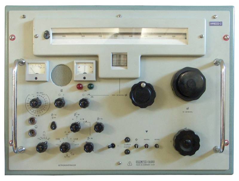
Maritime Receiver type 1340.21
Manufactured by RFT / VEB Funkwerk Köpenick, VEB Kombinat Nachrichtenelektronik, Köpenick; developed at Funkwerk Dabendorf.
In the early 1960s, Funkwerk Dabendorf and later Köpenick developed a series of maritime receivers to equip ship and coastal radio stations and other fixed radio services, they all carried a designation number 1340 followed by a suffix.
The bulky 1340.21 receiver seems to have found some inspiration from the Telefunken E104, a similar bulky receiver with a horizontal turret tuner.

Technical data
- Frequency range: 14 kHz - 30.1 MHz
- Frequency display: Analogue dial, dial accuracy with the interpolation oscillator activated better than 1 kHz.
- Frequency memory: none
- Sensitivity A1 below 100 kHz < 5 μV, 0.1 - 30 MHz 1 μV; AM (A3) 15 μV/ Selectivity: ±0.3 / ±0.6 / ±1.1 / ±2 / ±3.2 kHz (-6 dB)
Power supply
- Mains operation: 110, 127, 220, 240 V
Dimensions
- 565 x 450 x 460 mm, weight 60 kg
Accessories
- DM01 Demodulator for F1 (FSK) - transmissions
- DM03 Demodulator for SSB transmissions
- AD02 Antenna diversity set
Operation
The heavy set used in maritime radio and press radioteletype reception has a design similar to the Telefunken E104. With its dimensions of 56.5 x 45 x 46 cm, it has a weight of about 60 kg, the handles are not only decorative elements but a necessity if you want to move the heavy piece from its location.
The upper part of the front panel is dominated by the horizontal dial of the turret tuner. The huge knob in the right lower corner of the front panel is the bandrange switch.
In the middle is the display window of the interpolation dial resp. reference oscillator dial. On this dial, which has a 0 - 100 kHz division, the frequency between two 100 kHz calibration points can be read with an accuracy of less than half a kilohertz. To operate the set with the reference oscillator active, the corresponding switch is activated and the main tuning knob is used to tune to the next 100 kHz mark below the desired frequency. When the green lamp lights up, the main oscillator is locked; use the main tuning knob to move the pointer of the instrument to the centre position. When the pointer approaches one of the two red marks on the side, the main tuning must be readjusted for synchronisation. When the synchronisation is engaged, the reference oscillator tuning knob and its small 0 - 100 kHz dial can be used to adjust the frequency with an accuracy of 1 kHz.
To the left of the instrument for the reference oscillator, you find the monitor speaker and next to it the control instrument, which displays one of the different reference voltages, which are selected with the knob below it.
In the lower left corner are the switches for IF bandwidth (± 0.3 / 0.6 / 1.1 / 2 / 3.2 kHz) and operation mode, this control is coupled to the BFO. The RF gain can be controlled manually or automatically, the AGC decay time can be selected from 10 / 1 / 0.1 sec.
Technical principle
The set works as a double conversion superhet in most frequency ranges.
In ranges III and VII - IX it converts to a first IF of 700 kHz, in ranges X to XII it converts to a first IF of 1700 kHz, the second intermediate frequency is 100 kHz in all cases; this is also the case in ranges I, II, IV to VI, in which the receiver acts as a single conversion superhet with an intermediate frequency of 100 kHz. The five IF filters with bandwidths of 0.3 - 3.2 kHz operate on this IF.
The set has a 100 kHz IF output to feed optional external demodulators.
Components
Technical documentation
Development
The set has a modular design; individual modules can be replaced for easier repair.