Inhaltsverzeichnis
Wireless Set No. 12
Used by the Royal Signal Corps.
The British Wireless Set No.12 was developed in 1940/1, after a replacement for Wireless Set No.2 had already been considered in 1937. The transportable medium-power radio station replaced the Wireless Set No.2 and also replaced the Wireless Set No.1 and No.9 in many applications. For applications where higher transmission power was required to bridge longer distances, the set became Wireless Set No.12 HP (High Power) and Wireless Set No.33. (W.S. No.12 and power amplifier in the same cabinet). The set can be supplied with 100 - 225 V mains power, usually from a 250 W generator in the field, so it can be used on a lorry or as a fixed station.
Technical data
- Frequency range: 4 x SW (1.2 - 17.5 MHz)
- Frequency display: Analogue dial
- Frequency memory: none
Power supply
- Mains operation: 110 - 250 V
- Generator for mobile operation
Dimensions
- 605 x 310 x 390 mm, weight 54 kg
Accessories
Operation
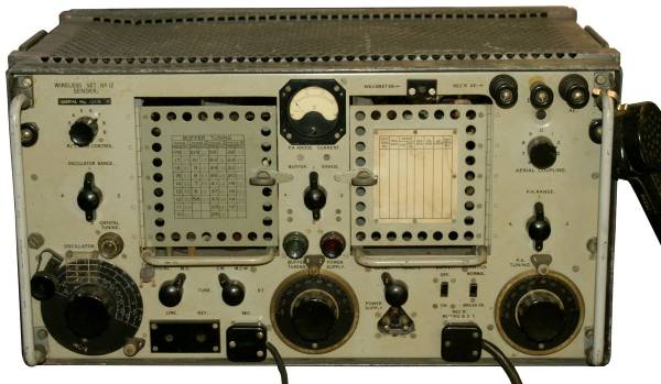
With a size of 60.5 x 31 x 39 cm and a weight of 54 kg, the transmitter of the Wireless Set No.12 is a heavyweight. An R107 or R106 (National HRO) was generally used as the matching receiver.
The oscillator is located at the bottom left of the front panel of the Wireless Set No.12. It can either be tuned free-running in four ranges (1.2-2.55 / 2.5-5.3 / 5.2-10.5 / 10-17.5 MHz) in the shortwave range or crystal-controlled.
In TUNE mode, the desired frequency is set on the rudimentary dial at the bottom left or, in crystal-controlled fixed frequency mode, twice the crystal frequency must be set; if the crystal frequency and half the oscillator frequency match, the CRYSTAL TUNING light illuminates. The next step is to tune the buffer stage, select the corresponding range with the switch above the tuning knob and tune with BUFFER TUNING from 180 degrees to maximum illumination of the BUFFER TUNING LAMP (approximate values are recorded on a BUFFER TUNING table), followed by tuning the output stage. Here too, the appropriate range is selected with the P.A.RANGE switch above the P.A. TUNING control and tuned to minimum plate current with the A.E. COUPLING switch in the O position with P.A TUNING.
The output stage is tuned by first setting a minimum plate current with the P.A. tuning control when the antenna or an artificial load is connected. In transmit mode with the Morse key pressed, the antenna coupling is then gradually increased until a minimum antenna current of approx. 80 mA is reached. (If you want to use your W.S.12 as an amateur radio transmitter, you should read the technical manual or the information in L. Meulstee's book, provided you have a valid amateur radio licence).
Compared to the transmitter of the Swiss Fahrbar Leichte Funkstation 40 of Zellweger AG, which was developed in the same time period, the English set looks quite archaic, the front panel is not very uniformly structured and the frequency reading accuracy is only arbitrary. The set was designed in no time at all in 1940 as a replacement for the obsolete W.S. No.2 from the 1930s. As an alternative to the W.S.33, a variant of the Wireless Set. No.12 HP (high power) was developed, and during the Second World War the set was replaced by the W.S. No.53.
Technical principle
The main oscillator in the transmitter is an ATS25 (V2a) in a Hartley oscillator circuit, the buffer or frequency doubler stage ATS25 (V2b) usually oscillates at the double frequency of the main oscillator. The output stage is an ATP35 (V3a) in a class C amplifier circuit, the antenna is decoupled via a capacitor and a switchable tapping of the antenna coil.
The signal can be decoupled for precise frequency determination using a wave meter.
The microphone signal is amplified in an ARP34 (V4a), after further amplification in an ATS25 (V2c), the audio signal is via a transformer to the suppressor grid of the RF final tube, the transmitter operates in grid modulation.\
Part of the output signal is fed to the output for the sidetone via a WX6 rectifier or, in later sets, via the more suitable EA50 diode and fed to the R107 tabletop receiver.
Components
The set is equipped with tubes.


